Memory Voltage Mod - Resistor Method (Continued)
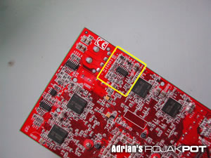
Turn off your computer and remove your card. Put your card in a clear and brightly-lit work space. Take a look at the same area outlined below.
This time, take a close look at the two points shown in the picture below. You will need to select one of these two points.
I recommend you select Point B because it is easier to solder your wire on that point. Soldering a wire to any pin is always harder and you run the risk of damaging that pin or adjacent pins.
You will need to connect a wire from either Point A or Point B to a variable resistor and connect the other end of the resistor to a ground point. You can use Pin 7 of the voltage controller chip as the ground point or simply solder it to a Molex connector's ground wire.
After you have soldered the wires and double-checked them, remember to set the 10,000 Ohm variable resistor to the highest resistance! Forgetting this step may cost you your card!
Then turn on your computer and measure the memory voltage again. The multimeter will record a higher memory voltage, even with the variable resistor set to its highest resistance.
Now, turn off your computer and give the variable resistor a slight turn to reduce the resistance a little. Then, turn on your computer and measure the memory voltage again. The multimeter will show an increase in the memory voltage. Repeat these steps until you attain your desired memory voltage.
Please try to keep to a maximum memory voltage of 2.9V. Although some insane modders have successfully kept their memory chips running beyond 3.0V, I recommend you keep below 3.0V.
Some of you may be wondering if it is possible to adjust the voltage "on-the-fly" - adjusting the variable resistor with the system turned on. Yes, that is possible. However, I strongly discourage you do that because an accidental twist of the variable resistor may inadvertently raise the voltage way too high and kill the memory chips.
Since this mod increases the thermal output of your memory chips, I recommend you add ramsinks to keep them cool.
<<< Memory Voltage Mod - Resistor Method : Previous Page | Next Page : Memory Voltage Mod - Pencil Method >>>


 Add to Reddit


