


 Add to Reddit

Building The MegaPak
Okay... you got everything? Let's get cracking!
- Take each single wire and strip about 5 mm of insulation from the ends of
each wire.
- Use the soldering iron to tin the ends of each wire with some solder.
- Take a look at the portable device's power port or jack in which you normally plug in the AD/DC adapter. Nearby, you should see a symbol like the picture shown below. It tells you what the polarity of the terminal points of the power jack should be. In this example, the inner terminal of the jack should be positive while the outer terminal should be negative. This is a very important step as mixing up the polarity will damage the portable device.
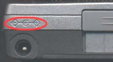
Power jack polarity
- Remove the cover of a female RCA plug to expose the solder points for the central terminal and the outer terminal (on a arm).
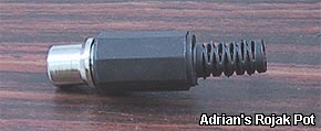
Female RCA plug
- Now, place the tinned end of a red wire on the central terminal of the power plug and solder it there.
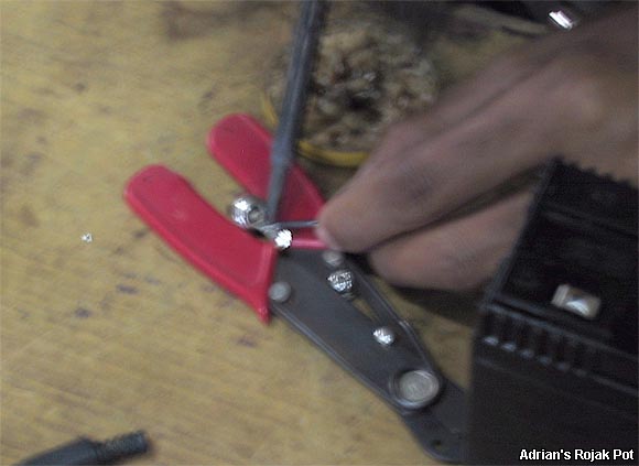
Soldering the wires to the female RCA plug
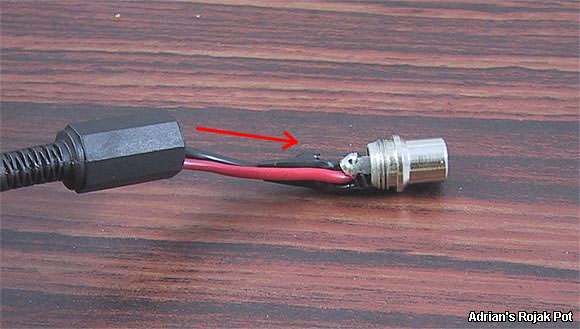
- Take the tinned end of a black wire and solder it on the arm of the outer
terminal.
- Alternatively, you can push it through the hole on the arm of the outer
terminal and solder it there.
- Once you have finished soldering both the red and black wires to the power
plug, cover at least one of the soldered point with tape to prevent short
circuits.
- Next, slip the power plug's cover over both wires and screw the cover over the lower part of the power plug.
Covering up the power jack
- Note that the red wire is now soldered to the positive (central) terminal
of the power plug while the black wire is soldered to the negative (outer)
terminal.
- Create any many of the power plug-wire combination as you need. In this project, I created two of them so that both my digital camera and Pocket PC can run off the SLAB. Two connectors also allow the SLAB to be recharged while it's powering one of the devices.
<<< The ARP MegaPak Battery Extender: Required Components : Previous Page | Next Page : The ARP MegaPak Battery Extender: Building The MegaPak (Continued…) >>>