


 Add to Reddit

Building The MiniPak
Before I start, please note that the pictures were all taken after I assembled the unit. I didn't expect to find the parts here in this small town I'm currently living in. So, when I actually found them, I immediately built the whole thing. In my fervour, I forgot to take pictures of the process. So, forgive me if many important pictures are missing or if they don't correlate too well with the explanation. :)
- Take one end of the insulated wire and split it into two for a distance
of 2-3 cm.
- Note that one of the two insulated wires that make up the 2-conductor insulated
wire will have a normal red colour while the other will have a white stripe
that runs down the side.
- Cut the stripe-less wire about 5 mm shorter than the striped wire.
- Strip about 5 mm of insulation from each wire.
- Use the soldering iron to tin each end of the wire with some solder.
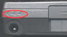
- Take a look at the port or jack in which you normally plug in the AD/DC
jack. Nearby, you should see a symbol like the picture shown below. It tells
you what the polarity of the terminal points of the power jack should be.
In this example, the inner terminal of the jack should be positive while the
outer terminal should be negative. This is a very important
step as mixing up the polarity will damage the Pocket PC.
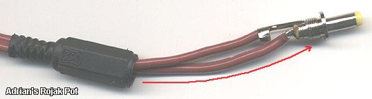
- Remove the cover of the power plug to expose the solder points for the inner
terminal and the outer terminal (on a long arm).
- Now, place the tinned end of the longer wire on the inner (central) terminal of the power plug and solder it there.

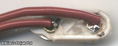
Solder points for the wires (Stripe-less wire top, striped wire below)
- Take the tinned end of the other (stripe-less) wire and solder it on the
arm of the outer terminal.
- Alternatively, you can push it through the hole on the arm of the outer
terminal and solder it in the groove on the other side of the arm.
- Slip the power plug's cover over the other end of the wire and pull it up the entire length of the wire.
Covering up the power jack
- Screw the cover over the lower part of the power plug.
- Note that the striped wire is now soldered to the positive terminal of the
power plug while the stripe-less wire is soldered to the negative terminal
of the power plug.
- Now, look at the connector cap for the battery holder. The male terminal must be negative while the female terminal must be positive.
![]()
Polarity for the connector cap (not the battery holder!)
- This is totally opposite of the terminals on the battery holder. Here, the male terminal is positive while the female terminal is negative. Don't mix this up! :)
As you can see, on the battery holder, the female terminal
is negative while the male terminal is positive.
- Take the free end of the wire and split it into two wires for a distance
of 2-3 cm again.
- Cut the stripe-less wire shorter by 1 cm.
- Strip 3-4 mm of insulation off the end of each wire and tin them with some solder.
Wires soldered to the connector cap.
Note that the striped wire is longer than the stripe-less wire by about 1 cm.
- Place the tinned end of the stripe-less wire into the indentation on the
back of the male connector of the battery holder's cap and solder it there.
- Do the same for the striped wire on the back of the female connector of
the cap.
- Cover the battery holder's connector cap and attach it to the battery holder.
- Load your batteries into the battery holder.

Load 'em up!
That's it! You have just built the MiniPak (copyright ARP 2001, etc, etc... heheh...) battery extender! It's best to use a multi-tester to run a polarity test on the extender to make sure the polarity is correct before plugging it into your Pocket PC. You can never be too sure when you are playing with the Pocket PC's power supply. :)
<<< The ARP MiniPak Battery Extender: Required Components : Previous Page | Next Page : The ARP MiniPak Battery Extender: The Completed MiniPak Battery Extender >>>